Instructions Afterglow 1.x and 2.x
- Important Notes
- Assembly
- Connectors
- WPC Installation
- System 11 Installation
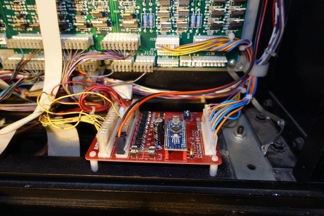
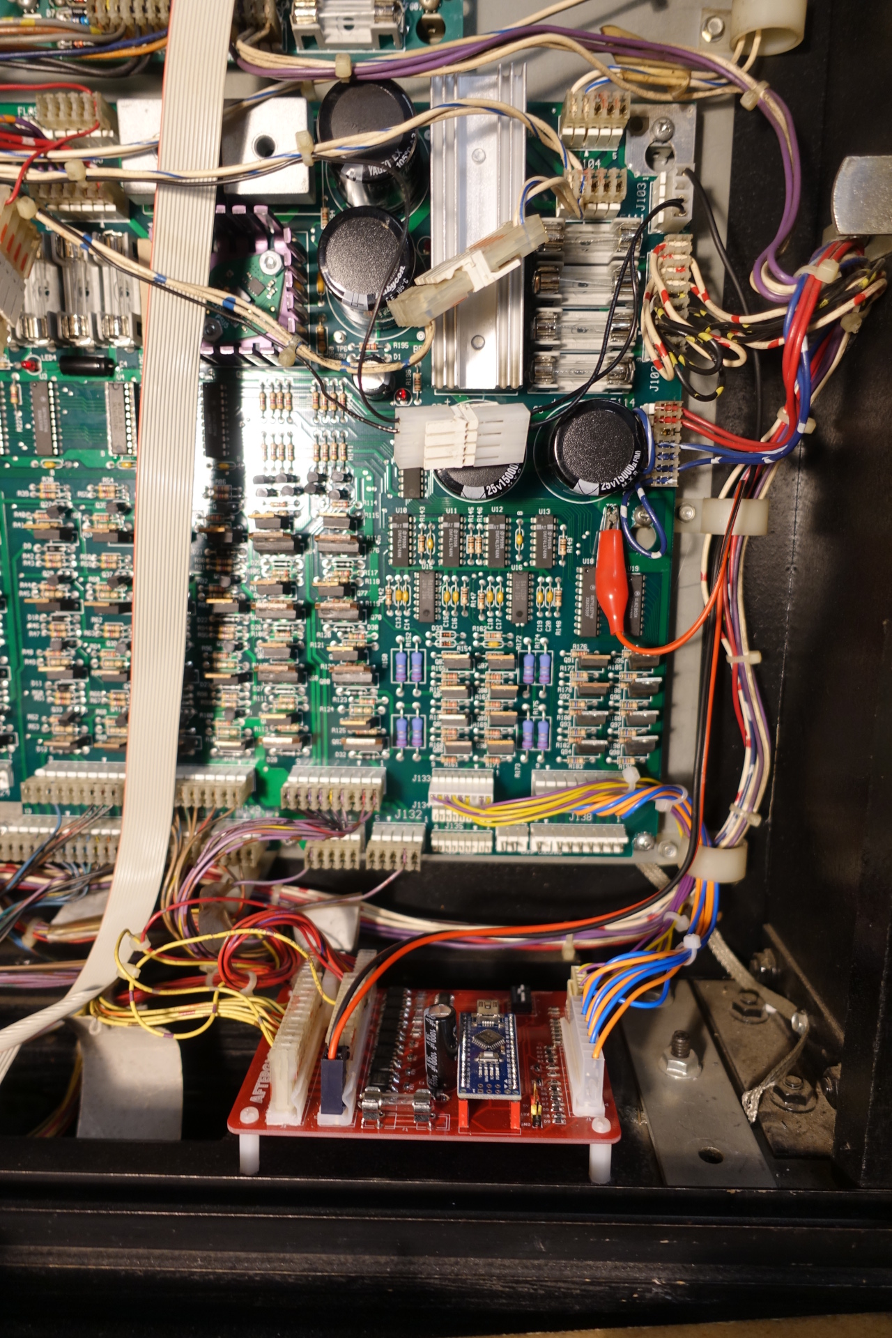
- Data East Installation
- Stern Whitestar Installation
- Fuse
- Firmware Upload
- Basic Feature Configuration
- LEDs
- Incandescents
- Pinball Machines
- Current board version is v1.5. Older revisions may have some limitations. Check the board revisions page.
- When using a v1.5 board using power from the columns then do not connect the + pin of the +/-18V connector. Only connect ground in this case.
- Board revision 1.3 has the J138 OUT connector pin 1 labelled on the wrong side! The pin labelled "1" is actually pin 9.
- When using the afterglow board, connect all WPC lamp matrix connectors to the afterglow board! Do not leave some of the connectors connected to the WPC PPD as it will cause undesired flows of current, damaging the input shift register.
- Switch 1 of the configuration DIP switch is inactive on board revisions 1.0-1.2 due to an unlucky pin assignment on the arduino.
- Regulating the input 18V to 5V requires some care. Please read the 5V page and choose a solution for your board.
Some tips for the assembly:
- Populate all SMD parts first, solder the connectors last
- Be careful when handling the MOSFETs, they are very sensitive to ESD damage
- Use pin header sockets for the Arduino - it would be very difficult to desolder it in case of problems

It's easiest to start with the SMD components as they have a very low profile. Next all ICs can be soldered, then all remaining parts. The MOSFETs are best populated last as they are the ones with the highest profile. Also, they are quite sensitive to ESD damage.

Some components are optional:
- The configuration DIP switch can be left unpopulated if you don't need the test modes
- Some of the output MOLEX connectors (J133_OUT-138_OUT) might not be needed. Check how many connectors are used in your pinball machine.
The PCBs from v1.1 onwards feature footprints for all 6 of the WPC lamp matrix connectors. However, most pinball machines do not use all of them, so you only need to populate the board accordingly.
In order to connect the afterglow board to the WPC power driver board you need to assemble two connector cables:
- One 9 pin .156" to 9 pin .156" cable
- One 9 pin .1" to 9 pin .1" cable
The length is approximately 20cm.
Board revision 1.4 can use the +18V from the column connector (J138 IN). Do not connect the "+" pin on the +/-18V connector when powering the board like this!
The board can still be powered directly from a 18V source. When doing this, remove the zero Ohm resistor (bridge) R67 in order to cut the power input from the columns.
You still need to connect ground (- pin of the +/-18V connector) to the power driver board!
The afterglow board needs to be supplied with 18V DC. The easiest way is to connect ground to a free pin on J103 on the WPC power driver board. The +18V can be hooked to the 18V test pin on the PDB with an alligator clip.
The Afterglow board needs to be connected to the WPC Power Driver Board with the two cables described above.
All lamp connectors (J133-J138) must be connected to the Afterglow Board. Do not leave Lamp connectors connected to the WPC PPD!
For board revisions 1.3 and earlier the +18V input must be connected to the power driver board's 18V test point.

The easiest location to mount the Afterglow Board is at the bottom of the backbox. This avoids having extensions for the lamp connectors. There is also a 3D printable PCB holder made by biglouie on Thingiverse.

The Afterglow board can be hooked between the System 11 CPU Board and the Interconnect Board. This way the lamps remain connected to the Interconnect Board. 18V power can be taken from the 1J4 and 1J5 connectors of the CPU board.

The Afterglow board can be connected directly to the Data East CPU board connectors CN6 (rows), CN7 (columns), CN4 (+18V) and CN5 (GND). For the output two adapter cables must be prepared.


The Afterglow board can be easily mounted at the right side of the backbox.
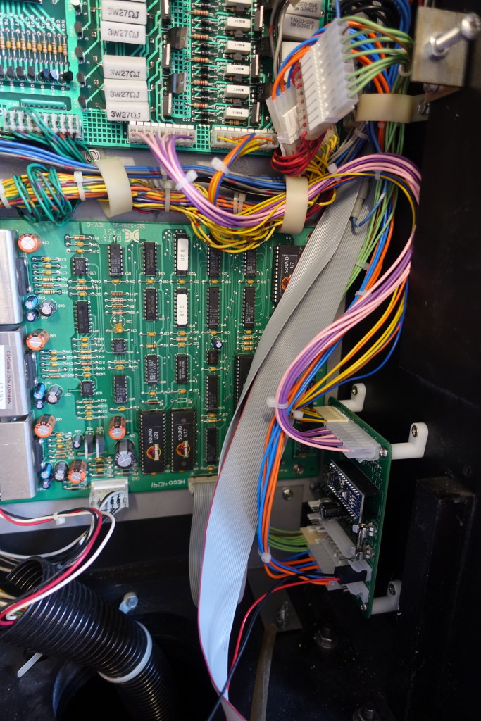
Installation in a Whitestar game is straightforward as power is available on the lamp column and row connectors (J13 and J12) on the power driver board. Note that the two power lines are unused on the original connectors.

The board should fit right on the unused sockets in the backbox left to the PDB.

I propose to use a 250V 2A slow fuse.
The firmware of the Arduino can be uploaded with the Afterglow Configuration Tool. It automatically fetches the latest revision from the repository.
Alternatively, the Arduino firmware can be uploaded with the Arduino IDE. You need to connect the Arduino on the afterglow board with your PC via a mini USB cable. Use the newest sketch from the repository.
The DIP switch (SW1) is used for basic configuration.

The current firmware uses following switch assignment:
- Switch 1 is used to enable test mode. In test mode some test patterns are played in a loop.
- Switch 2 is used to enable replay mode. If test mode is enabled (switch 1), turning switch 2 on will activate the replay of the recorded pattern. Note: The replay feature must be compiled into the firmware binary, otherwise this switch has no effect.
- (Firmware v106+) Switch 3 chooses the frequency of the matrix update. This has an effect on brightness of the lamps as well as the smoothness of the fading. If the switch is off, the frequency is set to 4kHz. If the switch is active 2kHz will be used.
- (Firmware v107+) Switch 4 enables pass-through mode. In this mode the input is replicated on the output directly.
Software configuration is done with the Afterglow Configuration Tool.