Instructions Afterglow 3.0
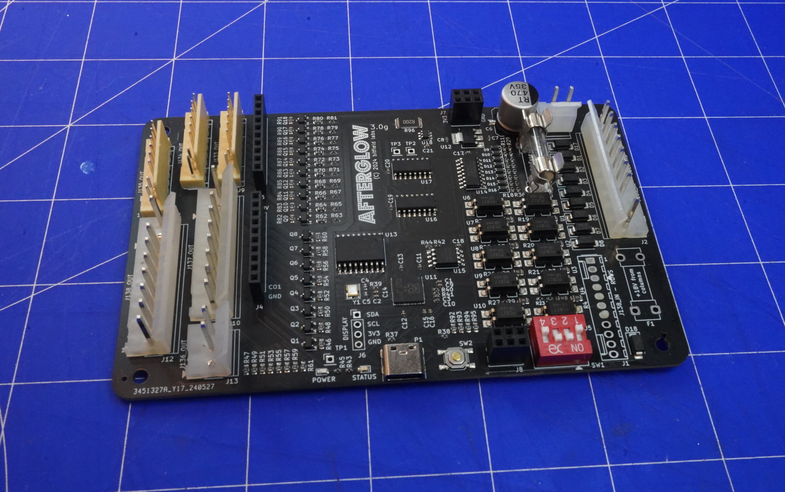
Current board version is v3.0g. Older revisions may have some limitations. Check the board revisions page.
💥 Board revisions up to 3.0g have wrong labeling of the input connectors:
-
J135_IN - COLUMNSshould beJ138_IN - COLUMNS -
J138_IN - ROWSshould beJ135_IN - ROWS
This board should be produced and populated in a factory. Some components like the RP2040 microprocessor are very hard to solder by hand. For JLCPBC there are BOM and Pick&Place files provided in the gerber folder.
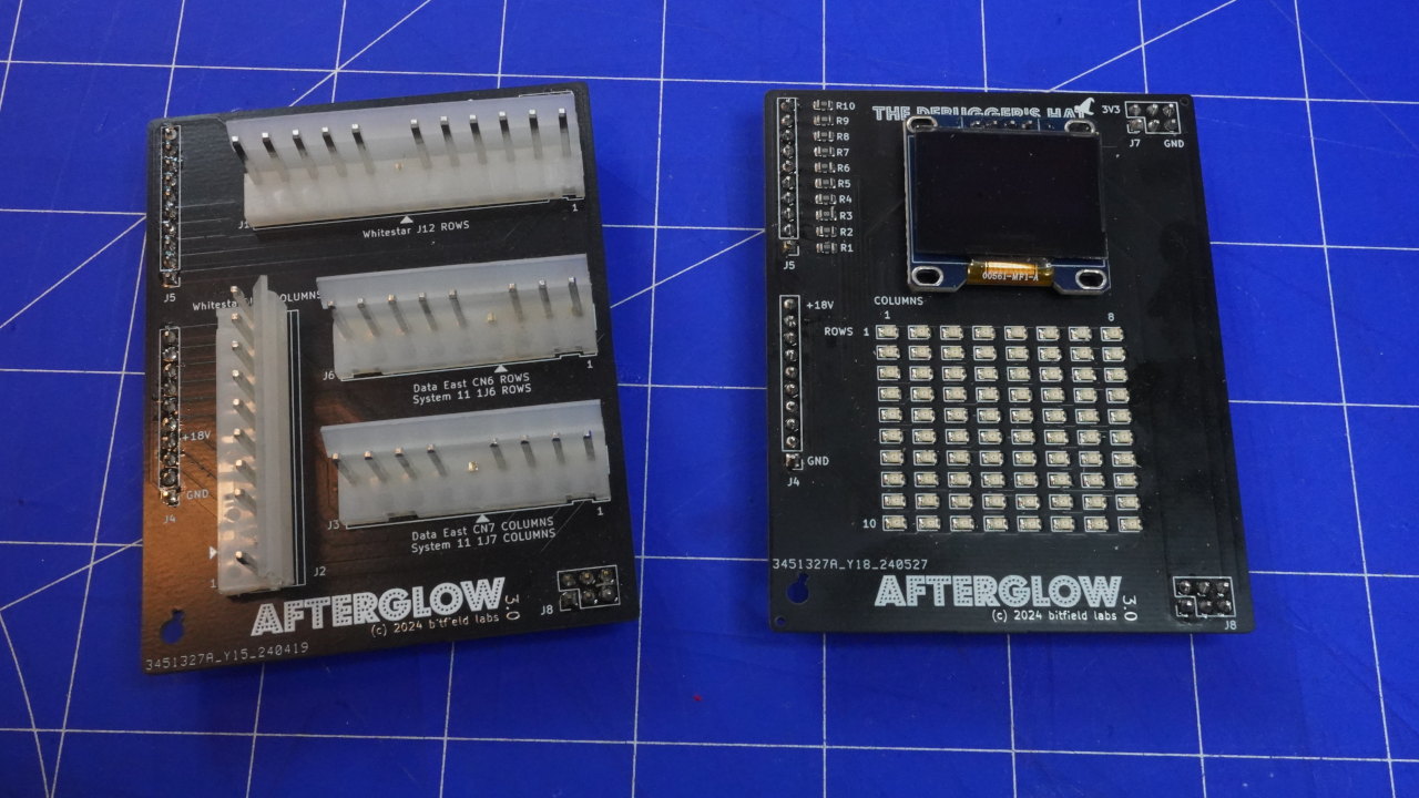
Afterglow 3.x feature support for hats in order to extend the functionality of the board.
In this picture you can see the pin bender's hat for System 11, Data East and Whitestar connection on the left side and the debugger's hat on the right side:
Note that v1.0 has a bug and creates a short between the i2c serial data line (SDA) and ground. This stops the RP2040 from working properly and freezes the afterglow board completely. This bug is fixed in v1.1. If you have v1.0 boards you can fix them by cutting the ground trace which connects the upper right pin of J8 to the ground pin on J4 on the bottom side of the PCB. Or just remove the upper right pin of J8 entirely.
The Afterglow board needs to be connected to the WPC Power Driver Board with the two cables described above. All lamp connectors (J133-J138) must be connected to the Afterglow Board. Do not leave Lamp connectors connected to the WPC PPD!

The easiest location to mount the Afterglow Board is at the bottom of the backbox. This avoids having extensions for the lamp connectors. There is also a 3D printable PCB holder in the repository and on printables.

This is analog to the WPC-89 installation, just with some changed connector naming and placement.

🎩 You need a Pinbender hat in order to connect the System 11 output to the Afterglow 3 board!
The Afterglow board can be hooked between the System 11 CPU Board and the Interconnect Board. This way the lamps remain connected to the Interconnect Board. 18V power can be taken from the 1J4 and 1J5 connectors of the CPU board.

🎩 You need a Pinbender hat in order to connect the Data East output to the Afterglow 3 board!
The Afterglow board can be connected directly to the Data East CPU board connectors CN6 (rows), CN7 (columns), CN4 (+18V) and CN5 (GND). The output connects directly to the Pinbender hat.

The Afterglow board can be easily mounted at the right side of the backbox.
🎩 You need a Pinbender hat in order to connect the Whitestar/S.A.M. output to the Afterglow 3 board!
Installation in a Whitestar game is straightforward as power is available on the lamp column and row connectors (J13 and J12) on the power driver board. Note that the two power lines are unused on the original connectors.

The board should fit right on the unused sockets in the backbox left to the PDB.
For all games two cables connecting the column and row signals to the Afterglow board plus a power cable need to be prepared.
Use around AWG 22 for signal cables (columns and rows) and AWG 18 for power cables. Also use AWG 18 for the column connector if you want to use +18V from the columns.
The PCB v3.0 allows to connect WPC machines directly on the PCB. See instructions below. The only difference compared to older revisions of the board is that the row input connector J138_IN is now a 11-pin connector which has two additional, unused row inputs on pins 10 and 11.
All 3.x PCBs feature footprints for all 6 of the WPC lamp matrix connectors. No connector hat is required for WPC-89 and WPC-95 games.
In order to connect the afterglow board to the WPC power driver board you need to assemble two connector cables:
- One 9 pin .156" to 9 pin .156" cable
- One 9 pin .1" to 11 pin .1" cable
The length is approximately 30-40cm.
Ground can be connected to any free pin on J103. If +18V is not taken from columns it can be connected to the corresponding test point on the PDB.

In order to connect the afterglow board to the WPC-95 power driver board you need to assemble two connector cables:
- One 9 pin .156" to 9 pin .156" cable
- One 9 pin .1" to 11 pin .1" cable
The length is approximately 30-40cm.
Ground can be connected to any free pin on J136 or J137. If +18V is not taken from columns it can be connected to the corresponding test point on the PDB.

Data East, System 11 and Whitestar/S.A.M. games are connected via the "pin bender's hat". Your pinball machine's original connectors plug directly to this hat.
In order to connect the afterglow board to the System 11 CPU board you need to assemble two connector cables:
- One 9 pin .156" to 9 pin .156" cable
- One 9 pin .156" to 11 pin .1" cable
The length is approximately 30-40cm.
Power can be taken from The J4 and J5 connectors on the CPU board.

In order to connect the afterglow board to the Data East CPU board you need to assemble two connector cables:
- One 9 pin .156" to 9 pin .156" cable
- One 9 pin .156" to 11 pin .1" cable
The length is approximately 30-40cm.
Power can be taken from The CN4 and CN5 connectors on the CPU board.

In order to connect the afterglow board to the Stern Whitestar and S.A.M. PDB board you need to assemble two connector cables:
- One 10 pin .156" to 9 pin .156" cable
- One 12 pin .156" to 11 pin .1" cable
The length is approximately 40cm.

The Afterglow 3.x boards can use the +18V from the column connector (J138 IN). This allows for using a simple ground only connection to the PDB board. Do not connect the "+" pin on the +/-18V connector when powering the board like this!
⚠ When installed in Stern Whitestar or S.A.M. games the power cannot be taken from the columns! Use the J3 power connector to feed +18V instead.
The board can still be powered directly from a 18V source. When doing this, remove the F1 fuse in order to cut the power input from the columns.
You still need to connect ground (- pin of the +/-18V connector) to the power driver board!
Use 250V 2A slow fuses for F1 and F2. F1 only needs to be populated when using +18V from the column input instead of providing +18V on the power connector J3.
The RP2040 firmware can be uploaded by putting the chip in firmware update mode. This is achieved by pressing the boot select button (SW2, next to the USB port) when powering the board. A mass storage device will appear on your computer (connected via USB). Copy the UF2 firmware binary provided in the repository to this drive. The chip will reboot automatically and run the new firmware.
When powered, the POWER LED should always be on.
The STATUS LED is indicating the device's current status:
- Off: No input detected, initialization mode
- Always On: Valid input detected, everything ok
- Slow blinking (1Hz): Test mode, replay mode, pass-through
- Fast blinking: Recording mode
- Very fast blinking: Invalid input detected
The DIP switch (SW1) is used for basic configuration.

The current firmware uses following switch assignment:
- Switch 1 is used to enable test mode. In test mode some test patterns are played in a loop.
- Switch 2 enables replay mode. In this mode a previously recorded pattern is replayed in a loop. Check the replay page for recording instructions.
- Switch 3 actives the smart mode. In this mode the board tries to identify lamp types, shorts and other lamp matrix behavior and automatically adjust the configuration accordingly.
- Switch 4 enables pass-through mode. In this mode the input is replicated on the output directly.
Software configuration is done with the Afterglow Configuration Tool.
There is no firmware update support from the tool at the moment. Please follow the instructions given here.
The MOSFETs on the board are powerful enough to drive incandescent bulbs too. A test with all legacy bulbs shows a power consumption of about 0.1A at 18V per bulb when it is fully driven. However, it is not recommended to have more than half of the lamp matrix populated with incandescents.